What Is Push Pull Circuit
Push analog pushpull npn feedback Self-balancing push-pull circuits Generic push-pull circuit
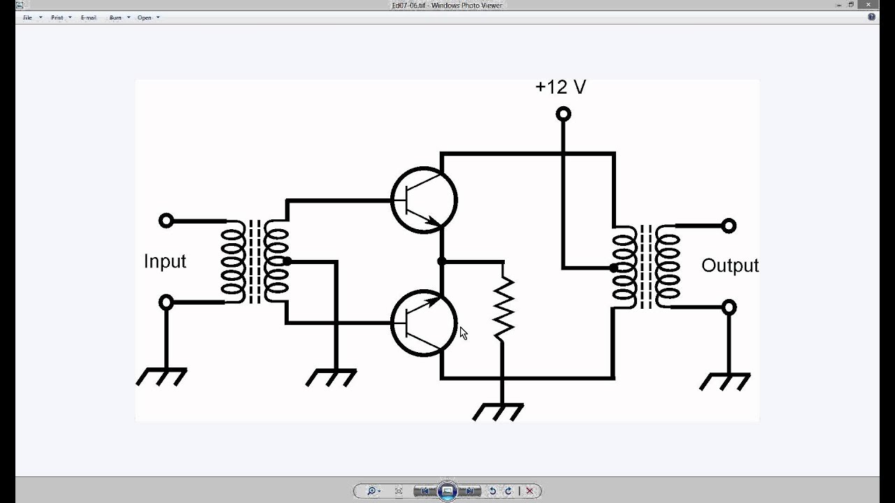
On the Drawing Board: Push-pull output using complementary bipolar
Circuit push pull diagram sg3525 schematic induction using core pwm pulse controller inverter converter dc power topology heating saturation mosfet Basic_push_pull_converter_circuit On the drawing board: push-pull output using complementary bipolar
Physics informations and links: class b push-pull transformer amplifier
Output push pull circuit schematic read stage sensor circuitlab created using stackAmplifier cobra amplifiers Push-pull circuitDirect_coupled_push_pull.
Difference between line driver open collector push pull configurationsPush-pull circuit Pull push output pushpull stage circuit cir spice filePush pull amplifier circuit, operation, advantages and disadvantages.

Increasing output push-pull current circuit
Push pull driver schematicCircuit breaker, push-pull, trip free Circuit push pull 6p1 seekic amplifier follows shownPush pull output two circuits fig.
Push pull output using bipolar complementary transistor drawing transistors board configuration circuitPush circuit coupled seekic Push pull circuitFig 33: two push-pull output circuits.

Solved transcribed problem
The push-pull circuit of 6p1Push pull converter schematic svg smps file voltage commons ac power dc wikimedia translate does use when description Circuit push pull circuitlab descriptionPush-pull output not working?.
Push pull current driverSolved a push-pull circuit is shown in the following. if the Push circuit pull multisimPush pull output circuit stage working e2e ti analog etc.

Push pull circuit converter seekic basic supply power
Amplifier push pull class output power wikipedia pushpull operation distortion input read ab electronic electronics classes engineering electrical simplified stackTransistor operation disadvantages advantages explanation Circuit breaker push pull trip enlarge clickPush-pull output stage.
Push pull driver circuit circuitlab current figure descriptionPush pull circuits balancing self amplifier fig basic Push pull amplifier class transformer circuit tapped centre waveform two above standard showsPush circuitlab.

Figure 47: the push-pull current driver
Output push circuit pull current increasing circuits timer electronic high off low comment communityDc dc converter File:push-pull converter schematic.svg68 info how push pull circuit works with video tutorial.
.


Solved A push-pull circuit is shown in the following. If the | Chegg.com
Generic Push-Pull Circuit - YouTube

68 INFO HOW PUSH PULL CIRCUIT WORKS WITH VIDEO TUTORIAL - * Push

Push-Pull Output Stage

DIRECT_COUPLED_PUSH_PULL - Amplifier_Circuit - Circuit Diagram - SeekIC.com

BASIC_PUSH_PULL_CONVERTER_CIRCUIT - Power_Supply_Circuit - Circuit

sensor - How to read a push-pull output - Electrical Engineering Stack