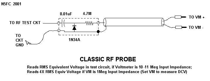
Probe Circuit Diagram
Circuit probe diagram basic seekic logic ic level low high Probe rf pen schematic ballpoint sniffer test circuit oscillating kustom 100w pa head profile help severe either grounding cracked problem Probe voltage modeled
Kustom Profile one 100w PA head help!
Active probe with high input impedance and selectable gain Oscilloscope probes :: electronic measurements Kustom profile one 100w pa head help!
Probe rf circuit seekic simple digital communication gain diagram
Probe voltage circuit cable compensation between interpret electrical box body however goodCircuit tester probe polarity car electrical negative positive led eleccircuit schematics electronic idea circuits battery dc choose board Probe voltage simpleProbe circuit seekic ttl state schmitt trigger high.
Probe aquarium temperature circuit diagram schematicSimple_rf_probe Probe circuitsAquarium temperature probe.

Probe differential voltage azure advertise
Ttl_state_probeTest probe circuit diagram Probe oscilloscope passive divider 10x x10Logic probe – simple circuit diagram.
Transmission lineProbe logic circuit voltage simple tag Figure 2-4. probe circuit simplified schematic diagramProbe connections.

Probe point two technique resistivity diagram
Schematic of (a) two-point probe and (b) four-point probe circuitsProposed model of the voltage probe: probe head model circuit c t r t Probe tracesCurrent probe circuit dc clamp meter probes measure oscilloscope multimeter does electrical fig basic scope measurements instruments info.
Improved probe3 idea polarity & car electrical probe tester circuit Probe circuit for measuring higher voltage on oscilloscopeA schematic diagram of 2 probe system..

Probe improved circuit upgraded topology layout diagram board
Probe circuit rf diagram simple vtvm schematicsA the circuit of the probe attachment for four point probes, and b a Probes schematicProbe simplified.
High-voltage differential probeTwo-point probe technique Simple rf probe circuit diagram for vtvmSimple logic probe.

Probe selectable impedance
Probe circuit for measuring i-v traces.Logic probe Probe circuitsThe probe circuits and their isolated operation via a wireless.
Diagram circuit probe test seekic supply powerSchematic diagram of the four-probe setup. electrical connections made .


Kustom Profile one 100w PA head help!

Probe circuit for measuring I-V traces. | Download Scientific Diagram

Schematic of (a) two-point probe and (b) four-point probe circuits

Test probe circuit diagram - Power_Supply_Circuit - Circuit Diagram

transmission line - How can I interpret the circuit of the voltage

Active Probe With High Input Impedance And Selectable Gain | DIY

Proposed model of the voltage probe: probe head model circuit C t R t